Design A Combinational Circuit With Three Inputs And Three Outputs
Q 4 5 Design A Combinational Circuit With Three Inputs X Y And Z And Three Outputs A B And C Youtube
Https Ece Uwaterloo Ca Msachdev Ece223 Assignment4 Solution 3rd Edition Pdf

Lecture 13 Problems Mano Ppt Video Online Download

Pin On Digital Logic Circuits

Design Of Parallel Adder In 2020 Binary Number Parallel Simple Solutions

Combinational Circuits Circuit Electronics Circuit Block Diagram
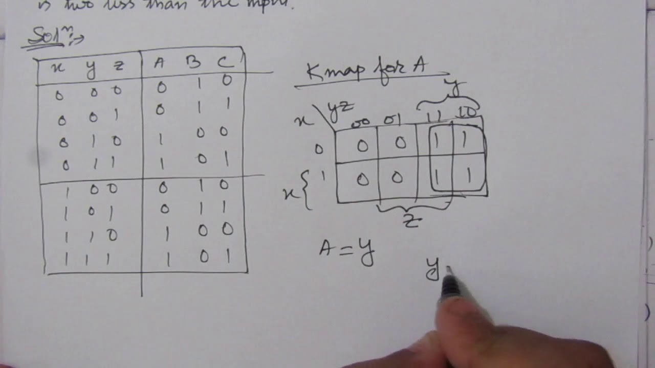
Given two input bits a and b produce three outputs x y and z so that x is 1 only when only when a b y is 1 only when a b and z is 1 only when a b learn more.
Design a combinational circuit with three inputs and three outputs.
Http Site Iugaza Edu Ps Aaldali Files 2015 01 Dd Assignment 2 Solution Pdf
Combinational Logic

Pin On Electronic Schematics
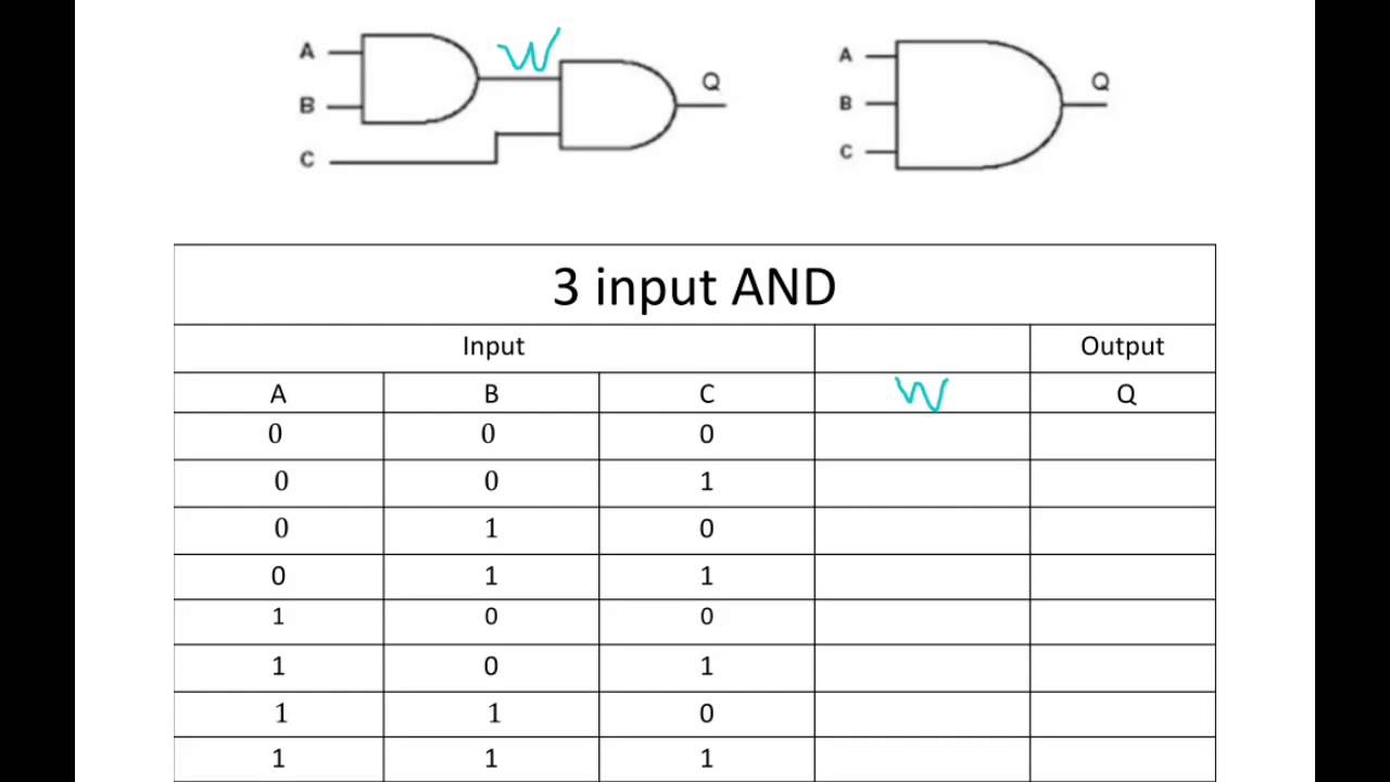
3 Input And Gate Truth Table Worked Out Youtube

2 Bit Synchronous Up Counter Electronics Circuit Circuit Digital

Unijunction Transistor Ujt Equivalent Model Circuit Electronics Area Transistors Circuit Electronics Components

Pin On Mrmgate

Simulation Of A Half Adder Circuit With 4 Basic Gates Using Tina Circuit Design Simulation Circuit Simulator

4 Bit Parallel Subtractor Parallel Logic Design

Power Supply For Audio Amplifier Circuit Multiple Output 12v 15v 35v Audio Amplifier Power Supply Circuit Basic Electronic Circuits

3 Bit Synchronous Up Down Counter Electronics Circuit Counter Circuit

Arduino Lcd With Tinkercad Wires Arduino Arduino Lcd Arduino Projects

Connection Of Potentiometer Google Search Resistors Voltage Divider Circuit

Digital Half Subtractor Design In Urdu In 2020 Electronic Engineering Digital Design

Different Types Of Amplifiers With Their Working Principle Electrical Projects Faux Fireplace Diy Entertainment Center Repurpose


Voltage Regulator Eee Electronics Power Engineering Electronic Engineering Electrical Projects
Https Www Bu Edu Eg Portal Uploads Computers 20and 20informatics Computer 20science 4887 Crs 12801 Files Solution Hw6 Pdf
Https Encrypted Tbn0 Gstatic Com Images Q Tbn 3aand9gcqnfsoufa5mvg Gozquyvyx7ts L395zjpoeorzdvabj7pxzsk2 Usqp Cau

Carry Select Adder Vhdl Code Coding Carry On The Selection

Gray To Binary Code Converter 4 Bit Coding Binary Converter

Tl084 Circuits Jfet Input Op Amp Datasheet Eleccircuit Com Basic Electronic Circuits Electronics Circuit Electronic Circuit Projects

Pin On Technology

Digital Flip Flop Circuits Explained Learn About Flip Flops And How To Trigger Them State Diagram Block Diagram Latches
Source : pinterest.com
